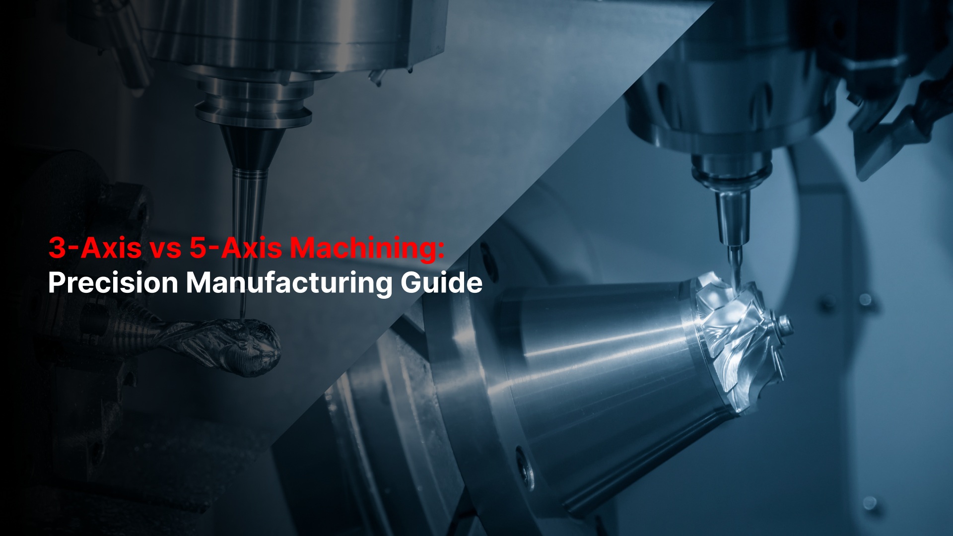
When your team runs precision components through production, machine capability decides how much control you have over quality, lead time, and repeatability.
Each CNC machine, 2.5-axis, 3-axis, or 5-axis- manages tool movement differently, and that difference shapes every step of machining.
The right axis configuration helps you balance efficiency with accuracy and reduce rework across batches. Understanding how these machines move, cut, and handle geometry gives you the insight to choose a process that fits your part design and inspection goals.
This guide explains the working principles, performance differences, and best-fit applications for each axis level. Let's go ahead.
Key Takeaway
Criteria | 2.5-Axis CNC | 3-Axis CNC | 5-Axis CNC |
Tool Movement | X–Y simultaneous, stepped Z | X, Y, Z move simultaneously | X, Y, Z + A, B rotary axes |
Setup Count | Multiple setups for different depths | Several setups for multi-face work | Single setup for most parts |
Geometry Capability | Flat or stepped features only | 3D contours accessible from limited angles | Complex surfaces, undercuts, and angles |
Programming Difficulty | Basic; short learning curve | Moderate; standard 3D CAM | Advanced; requires simulation |
Surface Finish | Good for planar surfaces | Reliable on accessible areas | Excellent across curved and angled faces |
Accuracy & Repeatability | Stable on simple parts | High, but alignment depends on re-fixturing | Very high due to single coordinate system |
Cycle Time & Throughput | Predictable but slower for complex parts | Moderate; setup adds time | Fastest overall with minimal handling |
Operator Skill | Entry to mid-level | Skilled 3D machinist | Experienced multi-axis programmer |
Cost per Part | Lowest on flat parts | Balanced for mid-complexity | Higher hourly rate, but fewer setups |
Ideal Industries | General machining, fixtures | Automotive, tooling, prototyping | Aerospace, medical, optics, defense |
Best Use Case | Simple plates, covers, brackets | Contoured housings, molds, and prototypes | Tight-tolerance, multi-angle parts |
What “Axis” Really Means in CNC
Every CNC machine removes material through controlled motion. The term axis refers to the direction and combination of those movements.
Each additional axis gives you more freedom to reach part features and reduce manual handling during production.
Linear and Rotary Axes
X-axis: left to right movement
Y-axis: front-to-back movement
Z-axis: up and down movement
A and B axes: rotary motions that tilt or rotate the tool or workpiece
Together, these movements define how efficiently a machine can reach every surface of your part.
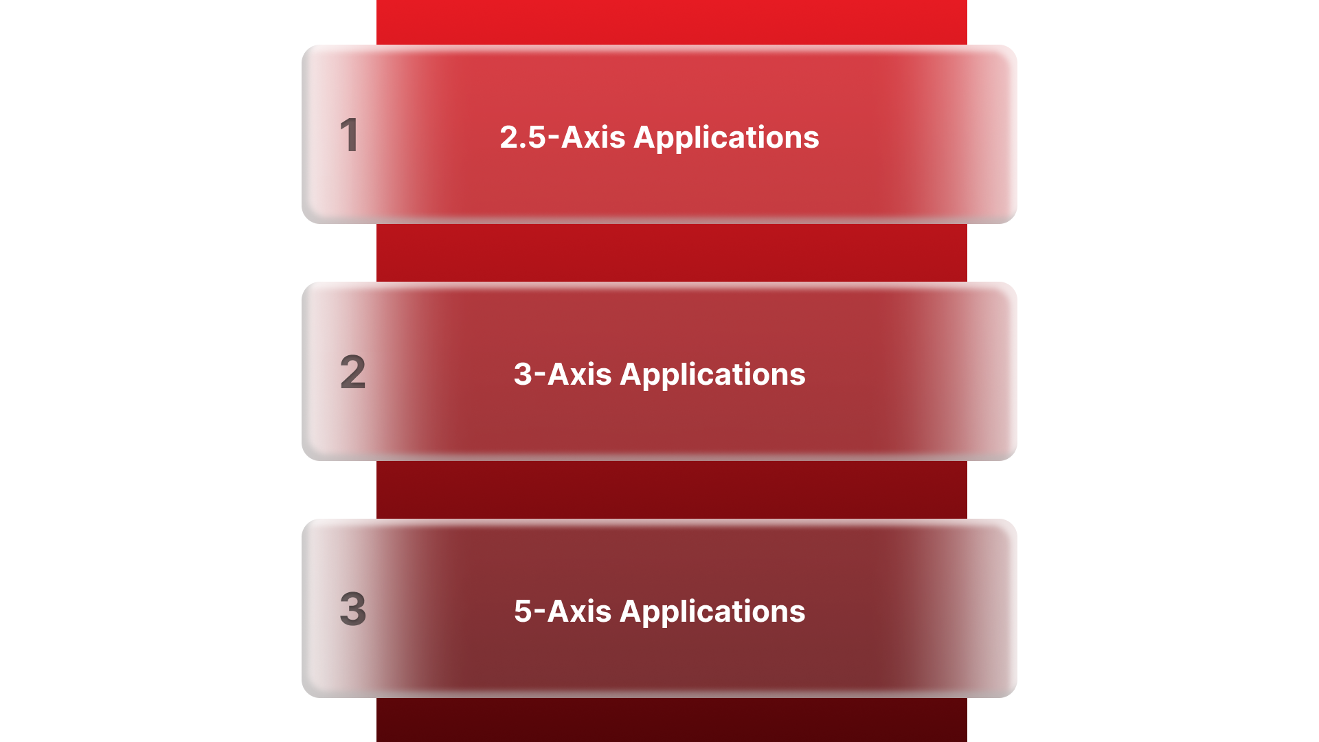
2.5-Axis Machining
The tool moves simultaneously in X and Y, while Z adjusts step by step.
Z motion occurs in layers — ideal for pockets, slots, and profiles that share one depth level before moving to the next.
Common for flat parts, covers, and brackets that do not require full 3D contouring.
3-Axis Machining
All three linear axes move together, enabling continuous 3D cutting paths.
Allows the creation of contoured or sculpted surfaces in one orientation.
Well-suited for molds, fixtures, and prototypes that demand smooth geometry transitions.
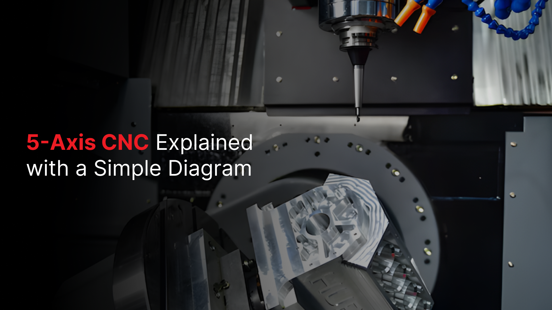
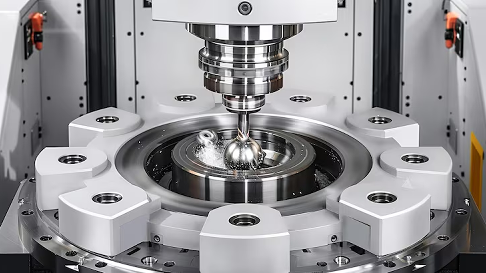
5-Axis Machining
Adds rotary motion on two additional axes for full part accessibility.
Supports angled features, curved faces, and undercuts in a single setup.
Helps maintain alignment across multiple surfaces without reclamping.
Manufacturers such as Criterion Precision Machining use 5-axis systems to produce complex aerospace and medical components where geometry accuracy and documentation integrity are essential for compliance.
Quick Comparison: Axis Fundamentals
Machine Type | Axes of Motion | Motion Behavior | Typical Applications |
2.5-Axis | X, Y (simultaneous) + stepwise Z | Flat layer-by-layer cuts | Pockets, plates, brackets |
3-Axis | X, Y, Z (simultaneous) | Continuous 3D cutting | Molds, housings, fixtures |
5-Axis | X, Y, Z + A, B (rotary) | Multi-angle machining | Aerospace, medical, optical parts |
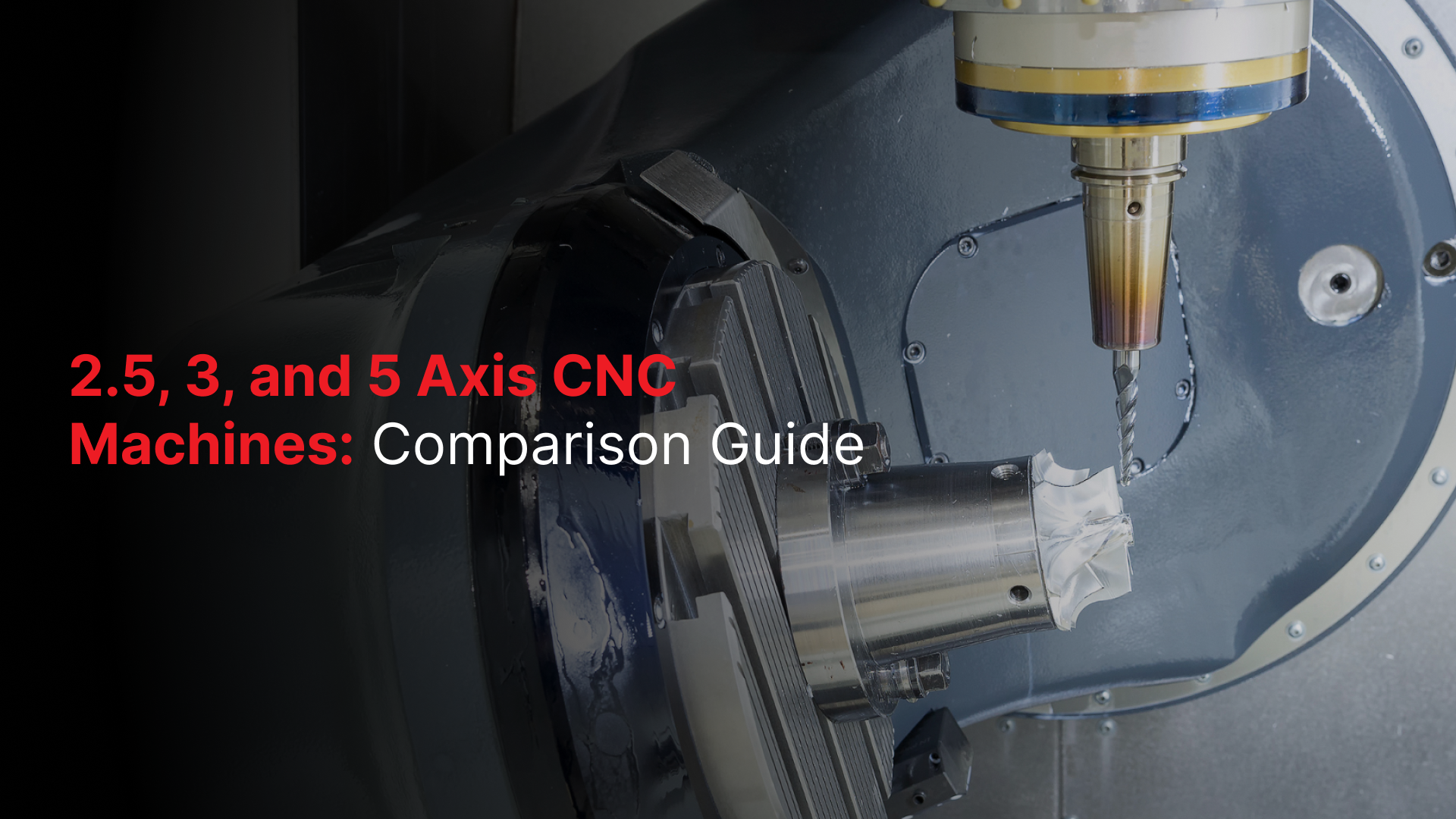
How Each Machine Moves and Cuts
The way a CNC machine moves defines how efficiently it can reach a surface, remove material, and maintain dimensional consistency. Understanding how each axis configuration behaves during motion helps you choose the most stable and cost-effective method for your parts.
2.5-Axis Motion
In 2.5-axis machining, the cutting tool moves in X and Y simultaneously, while Z adjusts in discrete levels.
Each layer of depth is machined before stepping down to the next.
Ideal for parts where most features lie on a single plane.
Simple toolpaths lead to faster programming and stable accuracy for flat workpieces.
However, since the Z movement is not continuous, contouring or sculpted shapes is not possible. Every surface must remain parallel to the machine table.
3-Axis Motion
3-axis machining enables full simultaneous movement across X, Y, and Z.
Allows smooth 3D cutting of curved or angled profiles.
The tool remains perpendicular to the work surface, so multiple sides require repositioning.
Best for parts that are accessible from a few fixed orientations.
Cycle times are longer on multi-face parts because each re-clamp adds setup time and small alignment variation.
5-Axis Motion
5-axis machines introduce two rotary motions, tilt and rotation, to access every face in one setup.
The tool can approach complex geometry from nearly any direction.
Steeper walls and undercuts can be machined without reorientation.
Tool length stays shorter, improving rigidity and surface quality.
This approach reduces handling time, minimizes tolerance stacking, and helps maintain consistency between design and inspection results.
Typical Parts, Features, and Use Cases
Different axis configurations suit different part types. Choosing the right machine depends on how many surfaces, features, and angles your design includes, and how much precision each requires.
2.5-Axis Applications
Flat plates, covers, and panels with stepped depths
Brackets and enclosures with holes or slots
Components requiring 2D profiling, pockets, or bolt patterns
Common in general machining, fixture bases, and sheet components
This setup is reliable for high-volume work where most features align on one plane and cycle time predictability matters more than geometry complexity.
3-Axis Applications
Fixtures, molds, and prismatic housings
Prototypes and mechanical parts with smooth 3D surfaces
Tooling and production components where several re-clamps are manageable
3-axis machines remain the backbone of most precision shops. They balance cost and capability for a wide range of materials and geometries.
5-Axis Applications
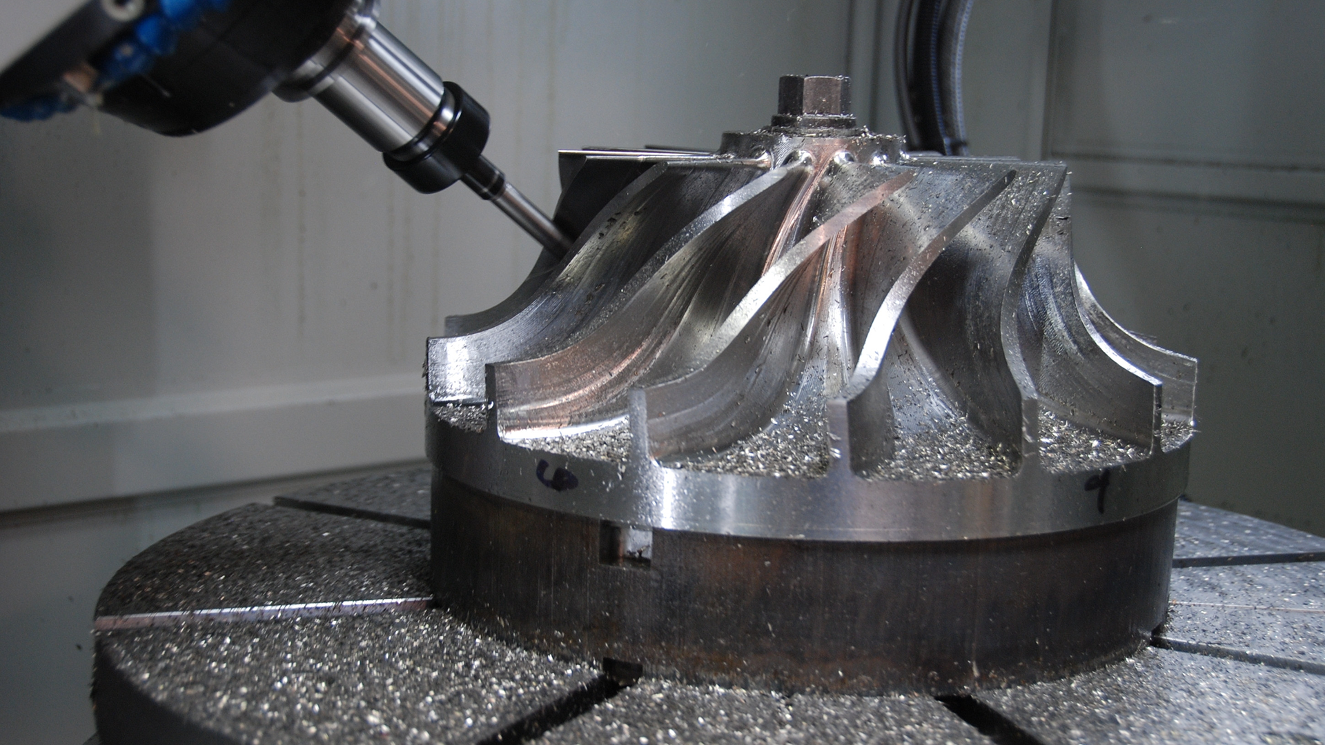
Aerospace brackets, turbine blades, and impellers
Orthopedic implants, surgical instruments, and optical housings
Components with multiple angled faces or curved surfaces
In operations where precision and surface continuity are critical, 5-axis machining provides higher geometric control in fewer setups.
Manufacturers such as Criterion Precision Machining apply this flexibility to support aerospace, defense, and medical programs where dimensional repeatability and documentation compliance are essential to production approval.
Accuracy, Surface Finish, and Geometric Capability
The number of axes on a CNC machine directly influences how accurately features align, how smooth surfaces appear, and how well geometric relationships hold across the entire part.
Accuracy in 2.5- and 3-Axis Machines
Both 2.5- and 3-axis machines can maintain strong precision on simple geometries.
Each setup adds a small amount of alignment variation; multiple re-clamps can cause cumulative error.
For parts machined on several sides, the relationship between features depends on how carefully each setup is referenced.
Surface Finish:
3-axis machines produce reliable finishes on accessible surfaces.
The tool remains vertical, so steep or angled features may need extra finishing passes or manual polishing.
Accuracy in 5-Axis Machines
Parts are usually completed in a single setup, maintaining a single reference system.
Rotary motion allows the tool to maintain optimal cutting angles across curved or inclined surfaces.
Consistent tool engagement produces smoother finishes and reduces tool wear.
Geometric Control:
Complex shapes stay true to the model because orientation shifts are software-controlled rather than manual.
Single-setup machining minimizes inspection corrections and scrap rates.
For regulated industries such as medical or aerospace, this level of precision helps maintain traceability between CAD data, inspection reports, and production outcomes, a requirement that Criterion Precision Machining integrates into every project.
Programming Complexity, CAM Requirements, and Learning Curve
Programming defines how effectively your machine turns a 3D design into an accurate physical part. As the axis count increases, so does the sophistication required in software and operator skill.
2.5- and 3-Axis Programming
2.5-axis programs are the simplest: mostly 2D profiles, pockets, and drilling patterns.
3-axis introduces true 3D toolpaths, contouring, and interpolation between planes.
Standard CAM systems handle these operations quickly with minimal simulation.
Programming time is short, and the skill requirement is moderate, ideal for shops with mixed workloads or short lead times.
5-Axis Programming
Requires advanced CAM platforms that can calculate dynamic tool angles and prevent collisions.
Simulation becomes essential to verify the tool's reach and movement before cutting.
Machine kinematics and post-processors must be calibrated to ensure code accuracy.
Programming time can double compared to 3-axis jobs, but fewer setups and reduced manual handling offset this.
To run multi-axis programs effectively, you need trained operators and strong process documentation.
Criterion Precision Machining combines Mastercam programming with integrated ERP traceability to maintain repeatable quality across both prototype and production jobs.
Setup, Fixturing, Throughput, and Productivity
How a part is fixtured and how many times it must be repositioned directly affect total cycle time, throughput, and process reliability. Axis configuration defines how much of this work happens automatically versus manually.
2.5- and 3-Axis Setup Characteristics
Require multiple setups to reach different sides of a part.
Each re-clamp introduces potential misalignment and adds non-cutting time.
Fixturing must be highly consistent to keep geometry within tolerance.
Manual setups extend lead time, especially for parts with several angled features.
This method suits production where geometries are simple, and batch volumes are high enough to justify repeatable fixtures.
5-Axis Setup Characteristics
Single-setup machining allows five-side access in one clamping.
Reduces handling, fixture count, and work-in-progress inventory.
Improves spindle utilization since less time is spent changing orientations.
Simplifies scheduling because one setup covers all critical surfaces.
Cycle times drop as non-cutting operations are minimized, and the likelihood of variation between runs decreases.
For OEMs in aerospace or medical manufacturing, this stability translates to shorter lead times and predictable inspection results.
Criterion Precision Machining applies automated fixturing and probing within 5-axis workflows to maintain consistency from prototype through volume production, helping your team hit delivery targets without adding inspection overhead.
Machine Cost, Operating Cost, and Cost per Part
Axis count also influences equipment cost, floor space, and hourly operating rate. However, the total part cost depends more on the balance between machining time, setup frequency, and rework prevention.
Equipment and Operating Cost
2.5- and 3-axis machines are more affordable to acquire and maintain.
Typical cost range: moderate capital investment, lower hourly rates.
Programming and operator training costs remain manageable.
5-axis machines require higher upfront investment and skilled labor.
Machine cost and software licensing are higher.
Operating rates rise with maintenance, calibration, and tooling demands.
Cost per Part Perspective
For simple geometries, 3-axis equipment maintains a clear cost advantage.
For complex parts, 5-axis machining often reduces cost per part by:
Eliminating secondary setups and fixtures
Reducing handling and rework
Lowering inspection and alignment time
The right economic choice depends on part mix and tolerance needs, not machine price alone.
Material Flexibility and Industry Application Fit
Axis capability affects how efficiently a machine can handle different materials, but rigidity, spindle power, and tooling strategy often determine final performance more than axis count.
Material Compatibility
All three machine types: 2.5, 3, and 5-axis, can process:
Aluminum, stainless steel, titanium, and specialty alloys
Engineering plastics and composites
The difference lies in how each handles tool access and cutting dynamics:
2.5-axis: best for softer materials or low-stress geometries.
3-axis: suitable for most metals and plastics with predictable surface loads.
5-axis: ideal for hard alloys or complex geometries that require shorter tools and smoother transitions.
Application Fit by Industry
General Manufacturing: 2.5 or 3-axis machines handle plates, fixtures, and enclosures efficiently.
Aerospace: 5-axis machining supports multi-face brackets and structural components.
Medical Devices: Single-setup machining minimizes burrs and ensures traceability.
Optics and Photonics: Tight geometry and surface finish benefit from dynamic tool positioning.
Criterion Precision Machining supports programs across all these sectors, applying the appropriate axis level for each project based on tolerance needs, compliance requirements, and delivery expectations.
When to Choose 2.5, 3, or 5 Axis: Decision Framework
Selecting the right axis configuration depends on more than machine capability; it’s a balance between geometry complexity, production targets, and available resources.
Choose 2.5-Axis When:
Parts are primarily flat or prismatic.
Features are accessible from a single direction.
Production volumes are high, and fixture repeatability is strong.
Programming simplicity and low operating cost are priorities.
Choose 3-Axis When:
Components include 3D surfaces or contours, but limited angled features.
You require a cost-effective option for molds, fixtures, or moderate complexity parts.
Cycle times can tolerate multiple setups.
Your team already manages 3D CAM workflows efficiently.
Choose 5-Axis When:
Parts include undercuts, compound angles, or curved surfaces.
Accuracy between multiple faces must remain consistent within a single coordinate system.
Lead time stability and inspection pass rates matter more than the machine's hourly rate.
Skilled programmers and process documentation are already established.
Decision Summary Checklist
Decision Factor | Best Fit |
Simple flat parts, high volume | 2.5-Axis |
Moderate 3D geometry | 3-Axis |
Complex shapes, precision-critical | 5-Axis |
Limited programming resources | 2.5 or 3-Axis |
Regulatory documentation required | 5-Axis |
Practical Buying and Implementation Tips
Investing in new machining capability is as much about integration as it is about equipment selection. A well-planned setup ensures your team gains full value from the machine’s axis capability.
Before Purchase
Evaluate facility capacity: confirm available floor space, power, and coolant systems.
Assess service coverage: choose brands with accessible US-based technical support and spare parts.
Check operator readiness: align training with the complexity of your planned programs.
Pilot parts first: benchmark cycle time, accuracy, and surface finish against your current setup.
After Installation
Calibrate tooling and probing systems: ensure geometry alignment across shifts and machines.
Integrate CAM software with ERP or quality systems: maintains traceability of tool paths and revisions.
Run time studies: compare setup and machining hours to validate ROI.
Standardize fixturing and documentation: reduces learning curves for future jobs.
Implementation Considerations
5-axis machining often requires investment in simulation software and tool management. However, once stabilized, the reduction in manual setups and rework can quickly offset the initial spend.
Conclusion
Axis count defines how much control you have over precision, efficiency, and consistency.
2.5-axis machines deliver dependable output for simple, high-volume parts.
3-axis machining balances cost and flexibility for most general applications.
5-axis systems handle complex, high-value components where geometry, surface quality, and documentation accuracy must align perfectly.
Selecting the right axis setup helps you reduce rework, stabilize lead times, and support long-term quality goals.
When your parts demand traceability, inspection-ready documentation, and tight geometric control, partnering with a certified, multi-axis supplier makes a measurable difference.
Criterion Precision Machining integrates 2.5-, 3-, and 5-axis machining under one quality framework, helping you meet compliance, delivery, and performance objectives with confidence.
FAQs
1. What is the main difference between 2.5-axis and 3-axis machining?
2.5-axis machines move X and Y simultaneously, but Z adjusts in steps. 3-axis machines move in all three directions together, enabling smooth 3D surfaces.
2. Can a 2.5-axis machine make 3D parts?
Not effectively. It handles stepped features but cannot contour true curved geometry.
3. Does 5-axis machining replace 3-axis completely?
No. 3-axis remains more cost-efficient for simpler parts and high-volume jobs.
4. Are 5-axis machines less accurate because they move more?
The opposite, single-setup machining improves alignment and reduces tolerance stacking.
5. Is 5-axis machining only for aerospace?
No. It’s also used in medical, optics, and precision industrial applications.
6. Why does 5-axis cost more per hour?
Higher equipment cost, CAM complexity, and operator skill, offset by fewer setups and less rework.
7. Do more axes always mean faster production?
Only when the part geometry benefits from fewer setups, for flat or simple parts, 3-axis may still be faster.